
Pressure relief valves (PRVs) are critical safeguards in oil and gas, refining, petrochemical, and process facilities. However, installing the correct PRV is only part of the job. The piping between the protected equipment and the PRV inlet can significantly affect valve stability and performance.
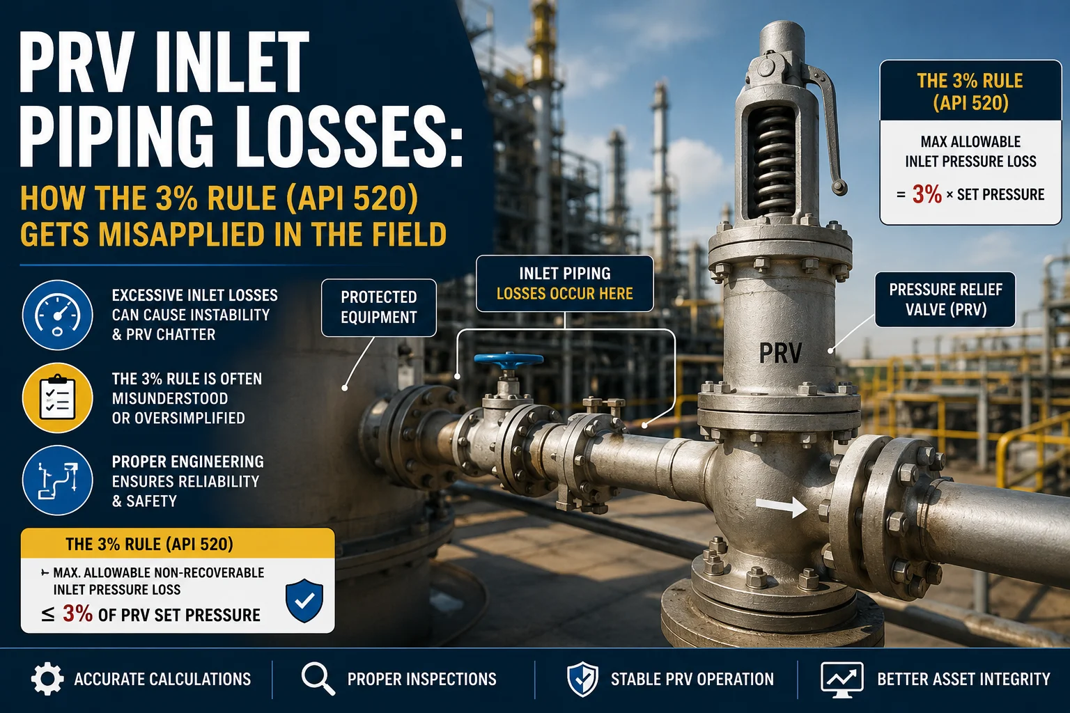
One of the most frequently discussed requirements is the 3% inlet pressure loss rule associated with API 520.
However, this rule is often simplified in the field to:
“The pressure drop in the inlet pipe must always be less than 3%.”
That interpretation is incomplete.
The intent is more specific. For conventional spring-loaded PRVs in relevant compressible-fluid applications, the concern is non-recoverable pressure loss at rated flow, because excessive inlet losses can contribute to valve instability, including chatter.
API 520 Part II specifically addresses PRV installation and PRV inlet piping losses, while API training material highlights the importance of engineering judgment when applying the 3% criterion.
The commonly referenced 3% criterion concerns limiting non-recoverable pressure loss in the PRV inlet piping.
In practical terms, engineers evaluate the pressure loss from the protected equipment connection to the PRV inlet under the applicable relieving condition.
The simplified relationship is:
Maximum allowable non-recoverable inlet pressure loss ≈ 3% of PRV set pressure
For example, if a PRV has a set pressure of:
100 barg
Then 3% would be:
0.03 × 100 = 3 barg
However, this does not mean every pressure drop calculation involving the piping should automatically be compared against 3%.
The actual engineering evaluation needs to consider the PRV type, service, relieving conditions, flow rate, piping configuration, and the applicable edition of the governing standard.
When a PRV opens, fluid accelerates through the inlet piping and into the valve.
If the inlet piping creates excessive pressure loss, the pressure immediately upstream of the PRV can behave differently from the pressure in the protected vessel or system.
That difference can affect valve stability.
For example, excessive inlet losses can contribute to:
Emerson’s pressure relief valve engineering guidance also explains how excessive inlet losses can contribute to unstable operation and destructive chatter.
Therefore, PRV inlet piping should be treated as part of the pressure protection system—not simply as ordinary process piping.
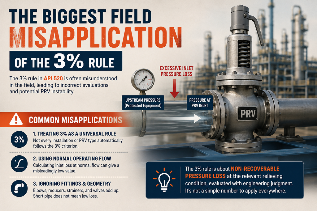
The most common mistake is treating the 3% value as a universal rule for every PRV installation.
A pressure drop calculation might show a certain loss through a pipe, elbow, reducer, or valve.
But the question is not simply:
“Is the pressure drop below 3%?”
Instead, the engineer needs to establish:
“What is the applicable non-recoverable pressure loss at the relevant relieving condition, and how does it compare with the applicable PRV stability criterion?”
That distinction matters.
Another common field error is calculating inlet pressure loss using normal operating flow.
PRVs, however, are designed to protect equipment during an overpressure scenario.
Therefore, the relevant hydraulic conditions can be substantially different from normal operation.
Consider these factors:
| Parameter | Normal Operation | Relief Condition |
|---|---|---|
| Flow rate | Normal process flow | Required relieving flow |
| Pressure | Operating pressure | Relieving pressure |
| Fluid properties | Operating conditions | Relief conditions |
| PRV status | Closed | Opening/flowing |
| Piping losses | Normal system loss | Relief-flow loss |
| Stability concern | Usually limited | Critical |
Consequently, using normal operating conditions can produce a misleadingly low inlet pressure-loss value.
A short pipe does not automatically mean low pressure loss.
The complete inlet path can contain:
Each component can contribute resistance.
Therefore, a proper PRV inlet piping calculation should evaluate the complete flow path rather than looking only at straight-pipe length.
Increasing pipe diameter generally reduces frictional pressure loss. However, pipe diameter alone does not tell the whole story.
For example, a nominally large inlet line may still have significant losses because of:
In other words, a large pipe does not automatically guarantee a compliant PRV installation.
This is one of the most important concepts to understand.
Not every pressure reduction in a piping system represents the same type of loss.
Some pressure changes can be associated with velocity effects and can partially recover downstream. Other losses result from friction and turbulence and are effectively non-recoverable.
The 3% criterion is concerned with the non-recoverable inlet pressure loss, not simply any pressure difference observed between two points.
That is why a basic pressure gauge comparison may not be sufficient for a proper engineering assessment.
Suppose a vessel is protected by a conventional PRV with:
A simplified 3% reference would be:
3% of 100 barg = 3 barg
The calculated loss is therefore above the commonly referenced 3% criterion.
However, the correct engineering response is not simply to label the installation “unsafe” based on that number alone.
The engineer should review the PRV type, relieving scenario, calculation basis, stability considerations, installation arrangement, and applicable requirements before deciding on corrective action.
Possible engineering solutions may include:
API 520 Part II includes an engineering-analysis approach for evaluating appropriate PRD installation.
A practical evaluation should follow a structured process.
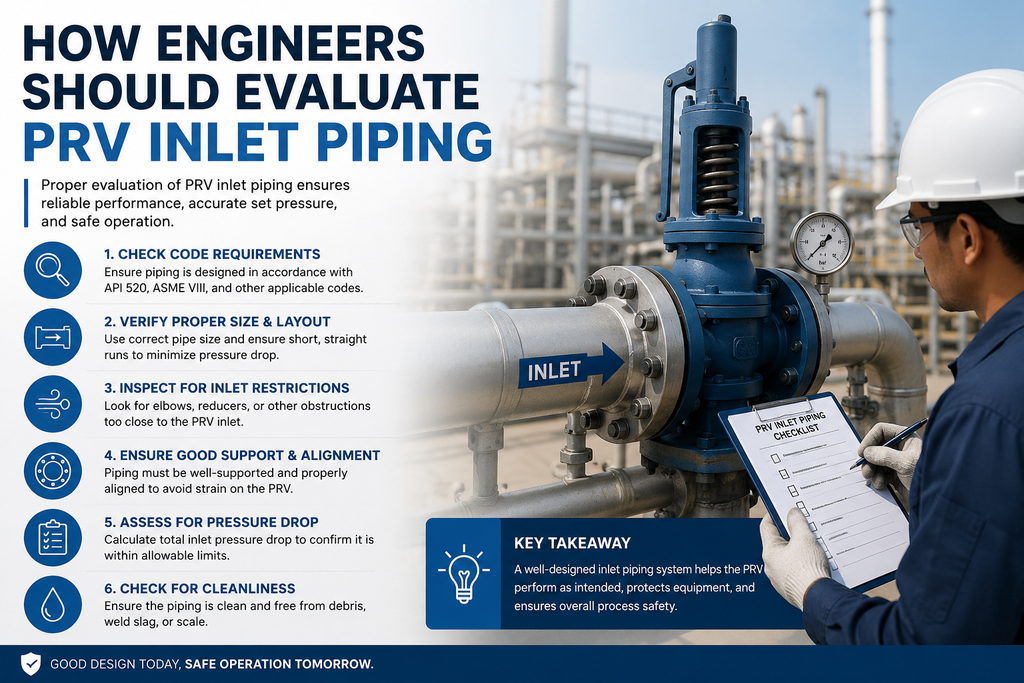
Start by confirming:
Identify why the PRV is expected to open.
For example:
The required relief flow depends on the scenario.
Document everything between the protected equipment and PRV inlet.
Include:
Use the appropriate hydraulic methodology and relevant relieving conditions.
The calculation should distinguish between recoverable and non-recoverable components where applicable.
Finally, determine whether the inlet configuration could create unacceptable PRV instability.
This is particularly important for conventional spring-loaded valves, where excessive inlet losses can contribute to chatter.
During design reviews, inspections, and plant modifications, teams should watch for several recurring problems.
Most importantly, a PRV installation should be evaluated using the actual configuration in the field, not only the original design drawing.
PRV performance depends on more than the valve itself.
Over time, facilities can change:
Therefore, inspection and engineering records need to remain synchronized.
A PRV that was correctly installed years ago may require reassessment after a modification to the upstream piping or process conditions.
For oil and gas inspection teams, managing PRVs through spreadsheets, paper forms, and disconnected reports can make it difficult to maintain a reliable inspection history.
InspectionsTrack provides a digital platform for managing inspection activities across oil and gas assets.
For PRV and pressure equipment inspection programs, teams can use digital inspection workflows to:
This becomes particularly useful when PRV inspection data needs to be connected with broader asset integrity and inspection management activities.
Instead of searching through separate spreadsheets and folders, inspection teams can maintain a centralized digital record of the asset and its inspection history.
The result is better traceability, more consistent inspection workflows, and less administrative work for inspection teams.
Before closing a PRV inspection or engineering review, consider checking the following:
The API 520 3% rule should not be treated as a simple “pressure drop equals 3%” field check.
It is part of a broader engineering assessment focused on PRV inlet pressure losses and valve stability.
Therefore, engineers and inspectors should consider the PRV type, relieving conditions, non-recoverable pressure loss, piping configuration, and applicable API requirements before determining whether an installation is acceptable.
Most importantly, don’t let a simple percentage replace engineering judgment.
A reliable PRV inspection program combines sound engineering calculations with accurate field data, documented inspections, and traceable asset history.
With digital inspection management software such as InspectionsTrack, oil and gas inspection teams can bring these records into one structured system and make PRV and broader asset integrity workflows easier to manage.
Read more : Dead Weight Tester vs. Digital Calibrator
The commonly referenced API 520 criterion limits non-recoverable pressure loss in the PRV inlet piping to approximately 3% of the valve set pressure for applicable installations. The requirement should be evaluated within the context of the applicable PRV type, service, and engineering analysis.
No. It should not be treated as a universal rule for every pressure relief device and every service. The applicable PRV design, service conditions, installation requirements, and engineering analysis must be considered.
Excessive inlet losses can contribute to unstable PRV operation, including chatter or rapid cycling. In severe cases, this can damage valve internals and associated piping.
The evaluation should consider the complete inlet flow path, including pipe length, diameter, fittings, valves, reducers, equipment connections, flow conditions, and the relevant relieving scenario.
Digital inspection software can centralize PRV asset records, inspection findings, checklists, reports, corrective actions, and inspection history, improving traceability and reducing reliance on disconnected spreadsheets and paperwork.
Technical note: API 520 Part I covers sizing and selection, while Part II covers installation. API currently lists Part II, 7th Edition as its published edition, and API’s standards committee is working on future revisions. Always verify the edition and requirements applicable to your project before using a specific criterion for design or compliance decisions.

Inspection companies in the oil and gas industry face a common challenge: how to handle more inspections, manage larger projects, and meet client deadlines without increasing administrative workload. As businesses grow, inspection teams must manage…

Meeting client Service Level Agreements (SLAs) is essential for inspection companies working in demanding industries such as oil and gas, energy, and industrial maintenance. Clients expect inspections to be completed on time, reports to be…


Comment (1)
Flare Stack Inspection: Rig Safety Checklist - inspectionstrack
Sep 04, 2026[…] Read more : PRV Inlet Piping Losses: How the 3% Rule Gets Misapplied in the Field […]
Comments are closed.